
Proofer Design
What is Proofer Design?
A proofer is a piece of equipment designed to provide a specific temperature and relative humidity conditions to boost yeast activity of the fermenting dough pieces.
Proofing equipment provides convective surface heating and conduction of heat from the dough surface to its interior. Typical proofing conditions essential for optimum quality yeast-leavened bakery products include:
- Temperature: 95–110°F (35–43°C)
- Relative humidity: 80–85%
- Cycle time: 40–70 minutes
How does it work?
Compared to ovens and other thermal processing equipment used in bakeries, design of high-speed proofers is less complex and can be operated at much milder conditions.
They range from manual to completely automated. Heat and humidity conditions are controlled by air conditioning systems that operate either by steam injection or water spraying (atomized), or a combination of the two.
Steam injection proofers
Saturated steam at low pressure, from a remote or built-in boiler, is released into the air to bring the internal proofer atmosphere to the humidity set point (%RH) for proofing. Temperature of the moist air is controlled by heat exchangers, usually radiators.
How does steam injection effect bread?
Water spraying proofers
Instead of using steam to increase the air moisture content, atomized water is sprayed from nozzles to maintain the dough’s moist external surface. The humid air is also heated by heat exchangers to set the required temperature.
Conditions provided by the proofer help ensure moist dough external surface moist. Formation of a dry skin is an indication of improperly functioning/designed proofer.
Aspects of proofer design
Designing bread proofers follows standard approach to equipment design, including:1,2
- Mass and energy balances
- Process modeling
- Process simulation
- Equipment sizing
- Equipment rating
- Equipment costing
Application
Proper proofer design, especially flow rates and capacity should be matched very closely to those of the baking oven. This helps in preventing issues with scheduling and minimizing idle times. Proofers considerably with larger capacity than baking ovens risk wasting capital and floor space.
Considerations for oven design:
- Product and pan dimensions (width and length)
- Pan capacity (dough pieces per pan)
- Shelf surface area required to proof a given number of pans (per shelf) at a given production rate (units/batch or units/min)
- Spacing between pans
- Capacity/throughput required plus long-term business growth (units/batch or units/min)
- Hygienic design (e.g. condensate collection and drain systems, elimination of dead cornes, cleanable surfaces)
- Mode of operation whether in batch (rack or cabinet proofers) or continuous modes where the dough pieces need to travel very long distances (1,500–4,000 ft or 460–1,220 m) to maintain normal proofing times (40–70 min for most breads and rolls)
The following are useful formulas for calculating the capacity of proofing equipment:
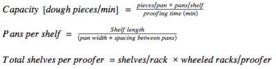
Capacity of continuous-mode proofers follow the same logic as batch proofers; the only difference is that the baking time in continuous equipment is controlled by the conveying speed.
Continuous proofers
Continuous proofing units are common in large-scale and high-speed bakeries. Their capital cost is considerably much higher than batch-mode proofers but they radically reduce labor cost and minimize production management issues.
They can usually provide automatic dough loading and unloading. Dough pieces travel resting on individual trays, shelves, moving racks or conveyor systems. This mode of operation improves product uniformity as each dough piece is exposed to the same proofing conditions throughout the travel length.
Engineering components to integrate in dough proofers design include:
- Electrical components (e.g. motors)
- Mechanical components (e.g. conveyors, gears, transmission belts, chains)
- Thermal components (e.g. source/generation of saturated steam, water atomizing systems/nozzles, steam dampers, insulation materials to minimize heat loses)
- Pan supporting systems
- Electronics and automation systems
- Instrumentation and control devices
- General construction components (e.g. equipment walls, supports, doors, racks, shelves)
References
- Maroulis, Z.B., and Saravacos, G.D. “Principles of Food Process Design.” Food Process Design, Marcel Dekker, Inc., 2003, pp. 37–87.
- Rahman, M.S., and Ahmed, J. “Food Process Design: Overview.” Handbook of Food Process Design, Blackwell Publishing Ltd., 2012, pp. 18–23.
